What is an LCD Controller Board?
A controller board is a piece in an electrical circuit that interfaces with a peripheral object by connecting the computer to it. The connection may be with other computer parts, such as the memory controller, or with an external device, like a mouse, that acts as a peripheral controller for an operation of the original device.
More information about TFT Technology you can find here:
What is an LCD Controller Board?
The LCD controller board is often called the Analog/Digital (A/D) board. As a type of hardware processor, it allows for various video source inputs to be connected, selected, and displayed on the LCD screen. It does this by converting the different video input signals into a format manageable by the LCD panel.

What is an LCD Driver?
In conjunction with the LCD controller, the LCD driver is a form of software that is the interface of and dependent on the controller piece. Combined, the two form an LCD controller driver board. As the controller connects the computer to the operating system (OS), the driver facilitates that communication. Though there is typically just one display controller per LCD, there can be added drivers to extend the reach of the drive to further segments of the LCD.
How does an LCD Controller Work?
To generalize the process, the LCD controller/driver adjusts the input signal, scaling resolution if needed, and then outputs the signal for the LCD monitor to use. Some of these output interfaces are low-voltage differential signaling (LVDS), SPI, I2C, and Parallel.
In most LCD controller/driver boards, there are two other input/output systems. Both these systems, however, are two-way pathways. One involves controlling and monitoring options, such as controls for brightness, image, and color using the on-screen display (OSD) control panel. The other is for communication via connections like Ethernet, Bluetooth, or IP.
The LCD board also contains an inverter that enables the lighting and powering of the LCD’s backlight. Typically, computers convert alternating currents (AC) of a wall power outlet into direct currents (DC); however, with the cold-cathode fluorescent lamp used in most LCDs, AC current is needed for power. This is the inverter’s job: to change DC back to AC. The original change from AC to DC is still necessary, nonetheless, as it allows the device to control the frequency used to drive the inverter.

Built into the LCD control board is the RAM, also known as on-board memory that stores the contents of the display. This RAM enables the drivers to communicate the content like desired voltage, current, and timing to the LCD display module and its pixels.
With modern developments, touch screen devices have become much more prominent, and so the touchscreen controller has as well. There are two types of touchscreens: the resistive one that measures pressure and the capacitive one that reads touch. In both of these, there are sensors that detect the touch signal which then transmit the signal data to the controller. The controller then processes the command for the OS.
To delve deeper into the details, consider the previously mentioned input signals. There are a variety of signals that LCD technology processes, such as VGA, HDMI, DVI, and DisplayPort. These computer display standards vary in format and characteristics like aspect ratio, display size, display resolution, color depth, and refresh rate. One of the biggest differences between these standards is their usage of analog signals or digital signals.
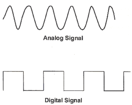
In an analog signal, the signal is continuous, but in digital, they are discrete values, typically of 0 and 1. Digital signals have become the most used, as they can more easily carry information and have better quality maintenance; if the analog signal is used and unnecessary information is present, it is impossible to remove it due to the continuous nature of the analog signal. In order to make that switch to digital signals, converters are used to replace the real numbers of the analog sequence with a set of discrete values.
The VGA, short for video graphic array, standard is one of the most popular analog-based technologies. In recent years, however, the VGA interface has been overshadowed by interfaces like high definition multimedia interfaces, better known as HDMI, which has become a de facto standard for digital signal transmissions.
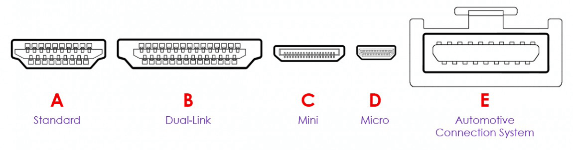
The HDMI is a combination of digital audio and digital video transmission. There are many HDMI connectors, such as the standard, dual-link, and micro. These connectors are what the input signal travels through to reach the LCD controller and to direct what to display.
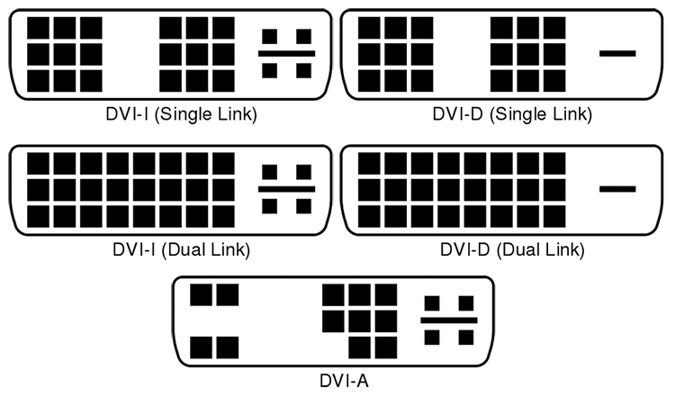
The DVI (Digital Visual Interface) offers both analog signals, digital signals, or a combination of the two. Like the HDMI, it has various connector types for different signal types.
When crossing interfaces, we use adapters to bridge the differences between signals. The DVI VGA adapter is relatively inexpensive due to how compatible the two are. The HDMI is also very compatible with the DVI, making the HDMI DVI adapter quite simple.
The VGA to HDMI adapter, however, must overcome greater differences, as they are not naturally as compatible as each were with DVI. Not only are there differences in the analog/digital signals, but also the VGA only uses video interface, whereas the HDMI uses both audio and video. A cable and an adapter are needed to connect the two devices.
And last from the list of examples of input signals is the DisplayPort. It is similar to HDMI in its purpose to replace outdated VGA and DVI as well as its transmission of audio and video through its interface. The DisplayPort does not have as much variation in cables and connectors as the HDMI, with only one cable and two types of connectors. From the DisplayPort, there is a growing technology called the embedded DisplayPort interface, or eDP interface. LCD manufacturers have begun to gravitate towards this interface due to its fewer connections, smaller size, and ability to quickly transmit high quality displays.

Bringing the subject back to LCD controllers, with the various types of computer display standards, the video signal inputs can be a challenge to accommodate and translate for the LCD panel, but with the help of adapters and the growth of these standard types, displays continue to become faster and develop with greater resolutions.
LCD Controller Board, right board for you?
LCD screens also have great variation. In order to decide if the controller board fits your LCD device, make sure to look at its datasheet to determine whether or not the controller board’s firmware, or its internal software, is compatible with the configuration of the panel. For instance, LVDS pins can vary in different LCD models, and between different brands, cables vary as well.
Features of High Resolution LCD Panel Controller Board
If a high resolution display is the goal, there are several features for the appropriate controller board that would enhance the panel’s properties. Here is a list of just a few features to look for:
Ultra-high definition (UHD) resolution; the controller board should support up to a 3840 x 2160 UHD resolution.
Ability to upscale the resolution of a signal to a UHD resolution.
Flexibility with the vast variety of input and output signals.
Understandable configuration and access to OSD for easy access to operating parameters and firmware updates.
Heater/fan activation based on device’s temperature for temperature management and control.
Pixel shift to prevent screen burn or persistence, or the discoloration of parts of the display due to a display that remains unchanged for a period of time.
How can I Reuse my Laptop Screen?
If your laptop is dead, but the LCD screen is intact, the laptop’s screen can be recycled into a monitor with the addition of an LCD controller board DIY kit.
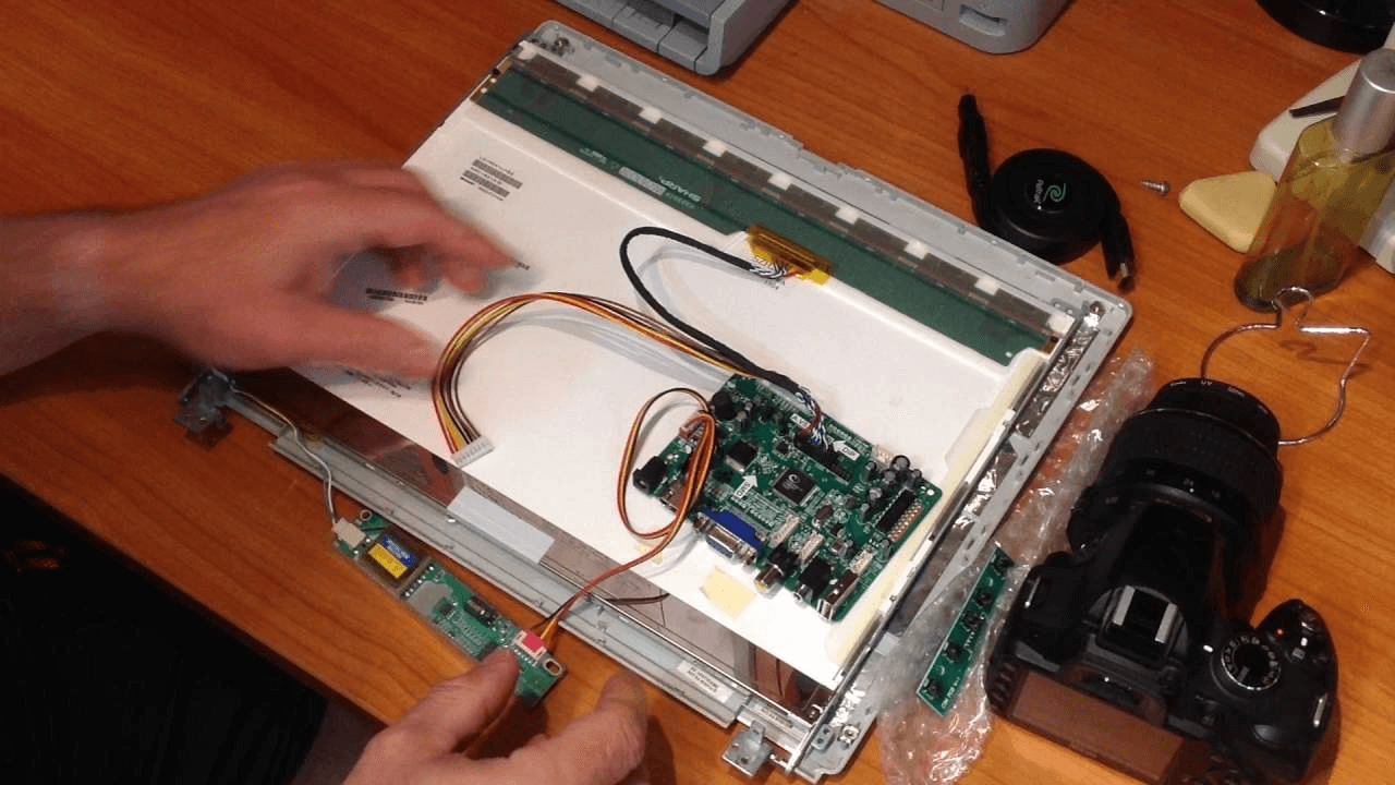
After unplugging the laptop and removing its battery, the screen can be removed using screws to release the frame and a careful prying of the frame to disconnect it from the laptop.
To remove the LCD screen, unscrew the screws attaching the panel to the laptop. There will be an LVDS cable attached that can be unplugged if the entire device is dismantled; it can also be cut at the bottom as they will be replaced by the controller board, but it is important not to cut the wires going into the inverter’s circuit board. Unplug the inverter’s two wires.
Once taken apart, the LCD panel can now be connected to the new board kit. Attach components with their respective parts: LVDS to panel, panel to inverter, transformer to control board, VGA to control board and operating computer. Then, press the power button on the control board.
The last steps are for the assembly of the device, including attaching a stand, attaching the LCD controller board, and screwing/connecting the device’s pieces back together.
Conclusion
Essentially, the LCD controller board is used for the conversion of input signals into panel-readable output signals to allow for the display of an image and potentially audio. Despite the various forms and components, controller boards can be incorporated into your own computer in a relatively simple fashion if the board is chosen to match your device.