1. What is LCD Display Image Sticking
Image Sticking refers to the persistence of a static image on a display screen even after the content has changed. Image Sticking, Image Retention, Residual Image, and sometimes also referred to as screen aging phenomenon (Burn-In), are terms used to describe the effect of static images on subsequent image displays. This can involve the rapid disappearance of previous static content or temporary lingering of aged images.
2.The definitions and causes of Image Sticking Display
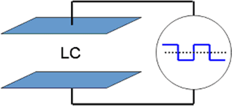
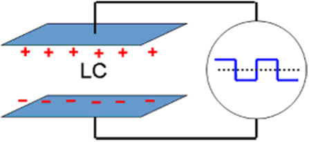
In TFT (Thin Film Transistor) displays, liquid crystal (LC) is a material with polar properties. An electric field can cause it to twist correspondingly.
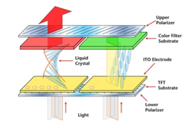
In TFT (Thin Film Transistor) displays, liquid crystal (LC) must be driven by alternating current (AC). If direct current (DC) were used, it would disrupt the polarity of the crystals. In reality, there is no such thing as perfectly symmetrical alternating current. When continuously driving the pixels of a TFT, tiny inherent imbalances attract free ions to the internal electrodes. These ions adsorbed onto the internal electrodes create a drive effect similar to a combination of DC and AC.
In display fabrication, there are 3 main reasons which can cause image sticking.
(1) Insufficient alignment capability
PI (Polyimide) material is responsible for liquid crystal alignment. The liquid crystals in the white grid area rotate, while those in the black grid area do not. The rotation of liquid crystals is influenced by both the external electric field and intermolecular forces. The interaction force between the PI (polyimide) molecules on the surface of the liquid crystal is greater than the external electric field force, so the liquid crystal molecules on the surface do not rotate. The closer to the middle layer, the greater the effect of the external electric field on the liquid crystals, and the rotation angle approaches the theoretical value. During continuous signal output, the liquid crystals in the white grid area affect the surface liquid crystals through intermolecular forces (electrostatic force and dispersion force). If the alignment capability of the PI film is poor, the pre-tilt angle of the surface liquid crystals will change as the liquid crystals rotate. In Figure C, when switching to a grayscale image, because the pre-tilt angle of the liquid crystals in the white grid area has deviated from that of the black grid area, under the same grayscale voltage, the liquid crystals in the region where the angle deviation has occurred are more likely to rotate to the theoretical angle, resulting in an increase in transmittance and thus causing image sticking.
(2) Impurity of Liquid Crystal Material
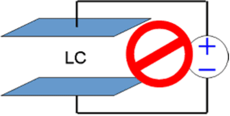
Asymmetric alternating current (AC) driving occurs in the pixel area, and the part of the voltage that deviates from the center is the direct current (DC) bias. The DC bias attracts impurity ions within the screen, causing ion accumulation and resulting in residual DC bias. When switching display screens, due to the effect of residual DC bias, liquid crystal molecules influenced by ions fail to maintain the state required by the design, causing differences in brightness between areas with ion accumulation and other regions, leading to undesirable image sticking.
(3) Distortion of Driving Waveform
By applying different voltages, the rotation angle of liquid crystal molecules can be controlled to display different images. Here, the concepts of γ value and Vcom need to be introduced.
In simple terms, γ value divides the transition from white to black into 2 to the power of N (6 or 8) equal parts. γ voltage is used to control the gradation of the display, usually divided into G0 to G14. The first γ voltage and the last γ voltage represent the same gray level, but they correspond to positive and negative voltages respectively.
To prevent the formation of inertial deviation in liquid crystal molecules, dynamic voltage control is required. Vcom voltage is the reference voltage at the midpoint of G0 to G14. Specifically, Vcom is usually positioned between the first and last γ voltages. However, in practice, due to differences in peripheral circuits, adjusting the match between Vcom and γ voltages is necessary. When Vcom is adjusted to its optimum value, the positive and negative frame voltages of the pixels are symmetric, resulting in equal brightness for both positive and negative frames. However, when Vcom deviates from the center value, the voltage difference between positive and negative frames of the pixels is no longer the same, leading to a change in brightness between positive and negative frames.
When the Vcom voltage is set incorrectly, it can cause charged ions inside the liquid crystal to adsorb at the upper and lower ends of the glass, forming an inherent electric field. After switching the screen, these ions may not be immediately released, or the liquid crystal molecules may become disordered during state transitions, preventing the liquid crystal molecules from immediately rotating to the desired angle.
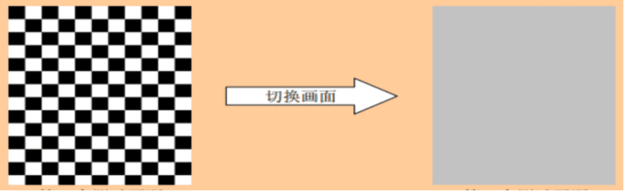
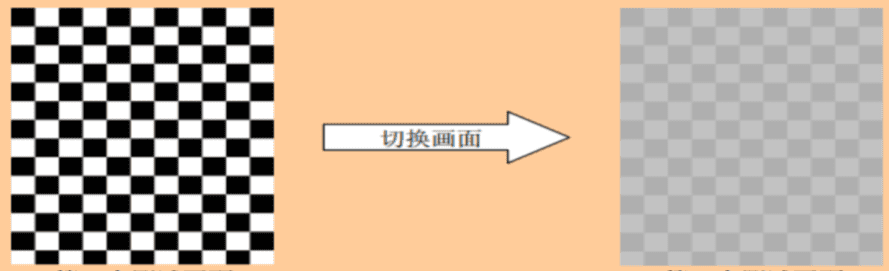
3.TFT LCD Image Sticking Testing
The following gives a fast-testing method:
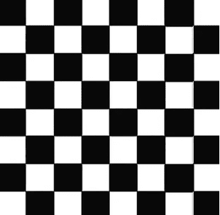
Room temperature; Displaying a black and white checkerboard pattern (each square approximately 60×60 pixels); Static display for 30 minutes. Displaying full-screen 128 (50%) gray; after waiting for 10 seconds, no ghosting visible is deemed as qualified.
(Note: This is a destructive reliability test, not a routine test.)
In a TFT with normal white, the white areas receive the minimum driving voltage, while the black areas receive the maximum driving voltage. Free ions within the TFT are more likely to be attracted to the black areas (those with higher driving voltage). When displaying full-screen 128 (50%) gray, the entire screen will use the same driving voltage, causing ions to quickly leave their previously attracted positions. Additionally, when displaying full-screen 128 (50%) gray, anomalies in the display are more likely to be noticeable.
4. Common Methods to Resolve Image Sticking Issues
1) Screensaver: When the system is idle, the pixels of the TFT display different content, either displaying a moving screensaver or periodically switching content, to avoid displaying static images for more than 20 minutes.
2) If the image sticking occurs already, leaving the TFT powered off for several hours presents an opportunity for recovery; (recovery may take up to 48 hours in some cases). Or creating an all-white image and moving it across the screen for several hours without turning on the backlight. There are many image sticking repair software available online that may also be helpful. Once ghosting occurs, it becomes more likely to recur, so proactive measures are needed to prevent the reappearance of image sticking in TFT LCD displays.
3) Adjusting the Vcom voltage to match the γ voltage helps prevent ghosting caused by residual voltage in liquid crystal molecules.
4) Adjust discharge timing to ensure rapid release of residual voltage in liquid crystal molecules. In circuit design, specialized voltages are typically used to control the first and last γ voltages. Here, VGH and VGL represent G0 and G14, respectively. If the discharge of VGH and VGL is slow during system sleep, it can also result in an excessive residual voltage in the liquid crystal molecules. When the system wakes up, there is a chance of ghosting occurring.
5) Image sticking on LCD screens typically falls under the category of functional defects in LCD displays and requires LCD panel manufacturers to perform adjustments. Generally, reputable LCD display panel manufacturers by using high quality orientation alignment PI material and high purity liquid crystal material will reduce the possibility of image sticking.
• Firstly, it’s important to confirm whether the current settings of VSPR/VSNR meet the glass requirements.
• Verify the optimal VCOM value, which can be determined by measuring the flicker value using CA210. A smaller flicker value indicates a better VCOM value.
• Re-scan the gamma and observe whether ghosting persists.
• Asymmetric Gamma: Typically, tuning symmetric gamma, where the absolute values of positive and negative voltages for each gray level are equal. This approach relies on the LCD glass’s VT curve being symmetric. However, if the VT curve of the glass is asymmetric, asymmetric gamma adjustment is needed.
• VT curve: A curve representing the relationship between liquid crystal voltage and transmittance.
• Asymmetric gamma typically occurs in two scenarios: 1) Overall polarity offset: In this case, one polarity is shifted overall. Adjustments to VSPR/VSNR are required to address this state. 2) Single or multiple order offset: In this scenario, specific points on the gamma curve need voltage adjustments to address the offset.