When designing a PCB board, designers must define the required board material materials for PCB construction. Therefore, designers predominantly consider two fundamental thermal and electrical properties, followed by mechanical properties.
PCB Material Thermal Properties
The thermal properties of a material determine its ability to withstand extreme temperature while maintaining its characteristics. The following are the thermal properties that need to be considered when selecting PCB materials.
Glass transition temperature (Tg)
Glass transition temperature (Tg) is defined as the temperature range in which a pcb material properties experiences transition from a rigid (glassy) state to a deformable (flexible) state since polymer chains start to move. Figure 1 below demonstrates the melting and softening phenomenon of the substrate. Between the glass transition temperature(Tg) and the melting temperature(Tm), the substrate reaches a rubbery state. Once the temperature is lower than Tg, the materials for PCB construction will harden, and the performance of the substrate will back to its original state. If the temperature is higher than Tm, the substrate will rapidly lose its shape as well as its strength since the material transforms from solid to viscous liquid.
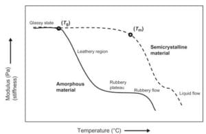
Figure 1: The state of the substrate
Decomposition temperature (Td)
Decomposition temperature (Td) refers to the temperature at which the substrate has a chemical decomposition, which causes the substrate to lose at least 5% of its mass. It is worth noting that if the temperature of the substrate reaches or exceeds Td, the subsequent changes in its properties are irreversible. Therefore, it is necessary to choose a material that can work well in a temperature range higher than Tg but much lower than Td. The Td of most PCB material properties is higher than 320, which is favorable as most soldering temperatures are in the range of 200-250°C.
Coefficient of thermal expansion (CTE)
The expansion rate of material when it heats up is called the coefficient of thermal expansion (CTE). The unit of CTE is in ppm(parts per million)/°C. Generally, the CTE of the dielectric substrate is higher than that of copper, which leads to interconnections problems when the PCB is heated. As the temperature of the dielectric material rises above Tg, the CTE also goes up. Since the woven glass restricts the material in the X and Y directions, even if the temperature of the material is higher than Tg, the CTE along the X and Y axes will not change much. As a result, the material will expand in the Z direction, but the CTE along this axis should be as low as possible.
Thermal conductivity
Thermal conductivity (k) is defined as the ability of a PCB material selection to conduct heat. In other words, the higher the thermal conductivity, the higher the heat transfer; while the lower the thermal conductivity, the lower the heat transfer. The expression of thermal conductivity is:
K= (Q * d) / (A * ΔT)
Q, d, A, ΔT and represent the amount of heat transferred, the distance between two isothermal planes, area of the surface, and temperature difference respectively. Compared with the thermal conductivity of copper (386W/M℃), the thermal conductivity of most dielectric materials is lower, ranging from 0.3 to 0.6W/M℃. This may explain why copper substrates will take away more heat than dielectric substrates.
Electrical Properties
Dielectric constant or relative permittivity (Er or Dk)
Dielectric constant or relative permittivity (Er or Dk) is defined as the ratio of material permittivity to vacuum permittivity. Most materials for PCB construction dielectric constants are between 2.5 to 4.5. The electric constant changes with frequency and is usually inversely proportional to frequency. Those materials that maintain a relatively stable dielectric constant over a wide frequency range are suitable for high-frequency applications
Dielectric loss tangent or dissipation factor (Tan or Df)
Dielectric loss refers to the inherent electromagnetic energy dissipation of dielectric materials. It can also be parameterized according to the corresponding loss tangent (Tan ) which is a phase angle between resistance and reactive current in the dielectric. The range of dissipation factor Df is from 0.001 to 0.030.
PCB Material Mechanical Properties
Tensile (Young’s) modulus or elastic modulus
Tensile modulus is a ratio of the stress to the strain along the same axis within the stress range applicable to Hooke’s law. The greater Young’s modulus value, the stiffer the substrate material. The expression is:
E = stress / strain = (F/A) / [(L – Lo) /L]
F, A, L, and Lo are the force applied on the material, the cross-section area of the material, the original length of the material, and the length of the material after being stretched, respectively.
Flexural strength
Flexural strength also called bend strength or transverse rupture strength, is defined as the stress before the PCB material yields when loaded in the center or supported at the end. The unit of flexural strength is in kg/m2 or psi.
Have more questions about how to choose materials for PCB? Contact our engineers today: tech@orientdisplay.com or visit our PCB page.
Check Also: PCB substrate
Reference:
https://www.sciencedirect.com/topics/materials-science/glass-transition-temperature
Circuits, S. (n.d.). PCB Material Design Guide. 1-30.