
Getting started with projects based on STM32G071RB Board using STM32CubeIDE
Check out our Control Board!
Getting started with a 32-bit ARM-based microcontroller is always a little daunting. There are too many of available microcontrollers, platforms, development boards, tools, and software. This note describes step by step how to begin a LED project.
Getting started: about Development Board STM32G071RB

Features:
- Core: Arm® 32-bit Cortex®-M0+ CPU, frequency up to 64 MHz
- Up to 128 Kbytes of Flash memory, 36 Kbytes of SRAM
- 7-channel DMA controller with flexible mapping
- 12-bit, 0.4 µs ADC (up to 16 ext. channels)
- Two 12-bit DACs, low-power sample-and-hold
- Two I2C, Four USARTs , one low-power UART , two SPIs
Getting started: Install STM32CubeIDE
You can download STM32CubeIDE from their st.com. It’ s free. Install STM32CubeIDE following STM32CubeIDE installation guide.
Your first project: LED blink
Before we can start writing code we need to create a project. This is similar to most other IDEs – projects are used to bundle together all of your settings, code, and definitions into a single collection all managed from the same application.


STEP 1: Start a new project, From the top left icon ( Or under the menu File > New > STM32 Project) to get started.

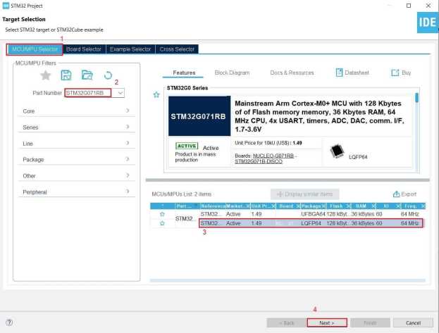
Step 2: Project name: G0_LED, then click Finish Button.

From schematic diagram that the LED4 is controlled by STM32G071 and the port is PA5.

Step 3: From System Core > SYS, select Serial Wire, setup PA5 as GPIO_OUTPUT.

Setup use label for PA5 as LED_GREEN as below:

Step 4: Then Generate code.

CubeIDE, which this functionality is developed upon, generates C files to work with under a Src directory, and puts a HAL (Hardware Abstraction Layer) into an Includes directory. It appears CubeIDE works the exact same way. Expand the folders on the right under the project view and see what it has generated to work for you.

Step 5: Let’ s add a smidge of C code of our own now! After the Infinite Loop area, we’re going to add code to toggle the LED under section 3 as below:

Compiling the project and downloading it to the board
STM32CubeIDE actually makes it pretty easy to compile our work and get it onto the STM32 chip. The first step is to produce the compiled .elf ( a binary version of our code). To generate the .elf, we need to do a build. This is as easy as pressing the build button on the toolbar.

Now, build information is presented in the console at the bottom of the screen.
 Now what we want to do is send this compiled binary onto the STM32 microcontroller.
Let’s plug in the dev kit:
 The Red power LED (to the left of the blue switch) is lit, as is the larger communication LED (by the USB cable). Inside STM32CubeIDE, select the run button.
 This will open the Run dialog ( as it’s the first time we’ve run it). The settings we choose now will be saved as a run configuration which we can re-use or edit later.
 Simply press Apply and then OK and the download will proceed. The Console will now fill with some interesting text:
 The LED is on and off every 500ms. you’ve got everything set up.