LCD and CTP Interface Introduction
For more information on LCDs, please see our LCD Basics tutorial page.
There are several ways of connecting MCU (Microcontroller Unit) or MPU (Microprocesser Unit) or CPU (Central Processing Unit) with LCD.
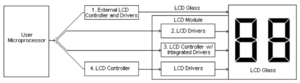
Fig. 1 Connection Between MCU to LCD
LCD Driving Waveform
LCD can’t be driven with DC (Direct Current), it has to be driven with AC (Alternative Current) and the overall current has to be ZERO. Otherwise, the Liquid Crystal Material will be damaged sooner or later.
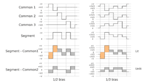
Fig. 2 LCD Driving Waveform
LCD Controller vs Driver
- There are two types of Driver IC’s, Common Drivers and Segment Drivers. Common Drivers output signals to create the rows or numbers of lines. The Segment Drivers output the necessary signals to create the characters or columns.
- The Controller IC receives data written in ASCII or JIS code from the MPU and stores this data in RAM. This data is then converted into serial character patterns and transferred to the LCD driver IC.
- Drive/Controller IC is probably the most commonly found in a graphics module. This IC receives data from the MPU and stores it in RAM. Also, it accepts commands directly from the MPU for both the common and segment drivers.
Parallel vs Serial Interface
- Parallel interface could transmit many bits data at same time depend on the data bits width.
- Serial interface could transmit just one-bit data at same time
MCU /Parallel Interface
- MCU interface include two types, 6800 and 8080. 8080 is the much more popular than 6800. Generally, MCU interface consist of 4/8/9/16bits data (like DB0, DB1, , , DB7; Note: 8bits is the most popular bits width), CS (chip select), RS (data register or instruction register select), RD (read enable), WR (write enable).
- PROs: Simple
- CONs: Need RAM, Speed is limited.
- Used in Mono character, graphic, small TFT (smaller than 3.5”)
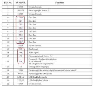
Fig. 3 MCU/Parallel Interface
Serial Interface
- Serial Interface include: I2C, SPI, RS232
- PROs: less connection, hardware lower cost
- CONs: Software is more complicated
SPI Interface
- SPI (Serial Peripheral Interface Bus) includes the following 4 wires:
- SCLK: serial clock (output from master);
- MOSI; master output, slave input (output from master);
- MISO; master input, slave output (output from slave);
- SS: slave select
- Used in Mono digit, character, graphic LCD, small TFT, some CTP
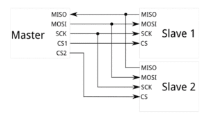
Fig. 4 4 Wire SPI Interface
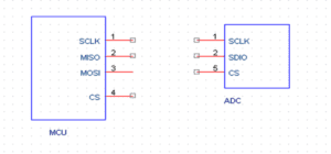
Fig. 5 3 Wire SPI Interface
IIC (I²C) Interface
- I²C (Inter-Integrated Circuit) includes the following 2 connections.
- SCL (serial clock wire),
- SDA (serial data and address wire).
- Used in Mono digit, character, graphic LCD, small TFT, most CTP
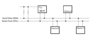
Fig. 6 IIC (I²C) Interface
RGB Interface
- RGB interface often been used in control large-scale high-resolution LCD display. It include 6/16/18bits data (like R0, R1, , , G0, G1, , ,B0, B1, , , ), VSYNC (Vertical synchronization), HSYNC (Horizontal synchronization).
- Advantage is that R,G,B data is written to LCD directly without GRAM, high speed. Normally used in large-scale high-resolution LCD.
- Disadvantage is to control LCD is more complex, and need more data wires than MCU interface.
- Application: Medium size TFT (3.5” to 8”)
- RGB interface includes 24 bit, 18 bit, 16 bit
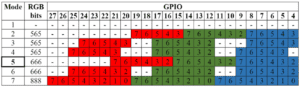
Fig. 7 RGB Interface
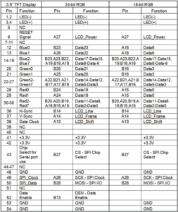
Fig. 8 Examples of 24 Bit and 18 Bit RGB Interface
LVDS Interface
- LVDS (Low-voltage differential signaling) is an electrical digital signaling standard that can run at very high speeds over inexpensive twisted-pair copper cables.
- Most used in big panels (>7”)
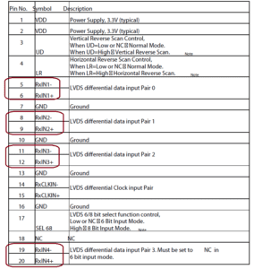
Fig. 9 Example of LVDS Interface
MIPI DSI Interface
- MIPI (Mobile Industry Processor Interface) Alliance, DSI (Display Serial Interface)
- Aimed at reducing the cost of display controllers in a mobile device. It is commonly targeted at LCD and similar display technologies. It defines a serial bus and a communication protocol between the host (source of the image data) and the device (destination of the image data)
- MIPI Interface is getting more and more popular.
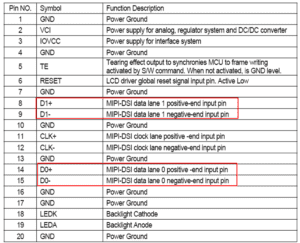
Fig. 9 An Example of MIPI Interface
eDP interface
DisplayPort (DP) is a digital display interface developed by a consortium of PC and chip manufacturers and standardized by the Video Electronics Standards Association (VESA). The interface is primarily used to connect a video source to a display device such as a computer monitor, and it can also carry audio, USB, and other forms of data.
DisplayPort was designed to replace VGA, DVI, and FPD-Link. The interface is backward compatible with other interfaces, such as HDMI and DVI, through the use of either active or passive adapters. It is mostly used for larger size and higher resolution displays.
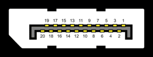
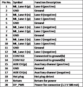
Fig. 10 eDP Interface
UART Interface
A universal asynchronous receiver/transmitter (UART) is a block of circuitry responsible for implementing serial communication. Essentially, the UART acts as an intermediary between parallel and serial interfaces. On one end of the UART is a bus of eight-or-so data lines (plus some control pins), on the other is the two serial wires – RX and TX.
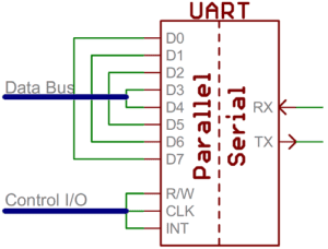
Fig. 11 URAT Interface
USB Interface
A Universal Serial Bus (USB) is a common interface that enables communication between devices and a host controller such as a personal computer (PC). It connects peripheral devices such as digital cameras, mice, keyboards, printers, scanners, media devices, external hard drives and flash drives. There have been four generations of USB specifications: USB 1.x, USB 2.0, USB 3.x and USB4.
It is widely used in capacitive touch panel connections.
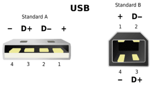
Fig. 12 USB Interface
HDMI Interface
HDMI (High-Definition Multimedia Interface) is a proprietary audio/video interface for transmitting uncompressed video data and compressed or uncompressed digital audio data from an HDMI-compliant source device, such as a display controller, to a compatible computer monitor, video projector, digital television, or digital audio device. HDMI is a digital replacement for analog video standards.
With more and more popular of color TFT LCD, HDMI is getting popular in display industry.
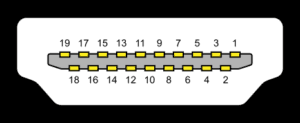

Fig. 13 HDMI Interface
RS232
RS232 is a standard protocol used for serial communication, it is used for connecting computer and its peripheral devices to allow serial data exchange between them. As it obtains the voltage for the path used for the data exchange between the devices.
- RS232 includes the following connections:
- RX
- VSS Signal Ground
- Vdd +5v
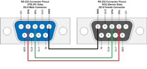
Fig. 14 RS232 Interface
RS-232, when compared to later interfaces such as RS-422, RS-485 and Ethernet, has lower transmission speed, short maximum cable length, large voltage swing, large standard connectors, no multipoint capability and limited multidrop capability. In modern personal computers, USB has displaced RS-232 from most of its peripheral interface roles. Few computers come equipped with RS-232 ports today, so one must use either an external USB-to-RS-232 converter or an internal expansion card with one or more serial ports to connect to RS-232 peripherals. Nevertheless, thanks to their simplicity and past ubiquity, RS-232 interfaces are still used—particularly in industrial machines, networking equipment, and scientific instruments where a short-range, point-to-point, low-speed wired data connection is fully adequate.
If you have any questions, please contact our engineers.